文献信息
Sillanpää et al., arXiv:0709.2341 (2007),“Coherent quantum state storage and transfer between two phase qubits via a resonant cavity”. arXiv:0709.2341 · DOI:10.1038/nature06124 原文为 arXiv 预印本版本的机器可读转换,公式与图注以原文为准;本页仅作站内索引与全文查阅,引用请以正式出版物为准。
全文
Coherent quantum state storage and transfer between two phase qubits via a resonant cavity
Mika A. Sillanpa¨a¨1, Jae I. Park1, Raymond W. Simmonds1
1National Institute of Standards and Technology, 325 Broadway, Boulder CO 80305, USA
A network of quantum-mechanical systems showing long lived phase coherence of its quantum states could be used for processing quantum information. As with classical information processing, a quantum processor requires information bits (qubits) that can be independently addressed and read out, long-term memory elements to store arbitrary quantum states1, 2, and the ability to transfer quantum information through a coherent communication bus accessible to a large number of qubits3, 4. Superconducting qubits made with scalable microfabrication techniques are a promising candidate for the realization of a large scale quantum information processor5–9. Although these systems have successfully passed tests of coherent coupling for up to four qubits10–13, communication of individual quantum states between qubits via a quantum bus has not yet been demonstrated. Here, we perform an experiment demonstrating the ability to coherently transfer quantum states between two superconducting Josephson phase qubits through a rudimentary quantum bus formed by a single, on chip, superconducting transmission line resonant cavity of length 7 mm. After preparing an initial quantum state with the first qubit, this quantum information is transferred and stored as a nonclassical photon state of the resonant cavity, then retrieved at a later time by the second qubit connected to the opposite end of the cavity. Beyond simple communication, these results suggest that a high quality factor superconducting cavity could also function as a long term memory element. The basic architecture presented here is scalable, offering the possibility for the coherent communication between a large number of superconducting qubits.
A particularly interesting quantum information architecture involves the interaction of matter and quantized electromagnetic fields, or cavity Quantum Electro Dynamics (QED). In some cavity QED systems, atoms, which can play the role of qubits, are passed through or are trapped within optical or microwave cavities with resonant modes matching one of the atom’s spectral lines. These systems14, 15 have enabled fundamental tests of quantum mechanics, as well as demonstrations of quantum memory and a quantum bus16. Recently, the Cooper pair box5 has been successfully incorporated into a superconducting resonant cavity in order to perform analogous experiments in the strong coupling regime, forming a new field known as “circuit QED”17–21. Similar resonant cavities have also been used to stabilize flux qubits22, and thus far experiments have found spectroscopic evidence for the entanglement between two phase qubits and a resonator23. In this work, we report the first time-domain measurements showing coherent interactions for circuit QED performed using superconducting Josephson phase qubits coupled to a cavity formed by a transmission-line resonator. Moreover, by coupling two phase qubits to a single cavity, taking advantage of the independent control of each phase qubit and single-shot readout, we have constructed an elementary quantum memory and quantum bus in a superconducting system.
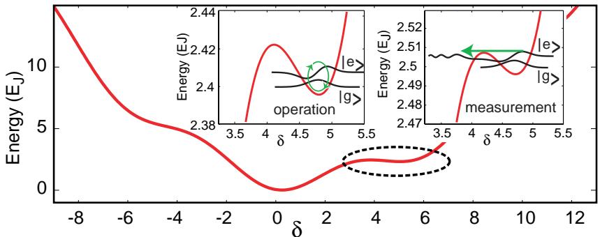
For a flux-biased Josephson phase qubit24, the ground state |gi and the first excited state |ei are encoded in the phase difference δ across a large-capacitance superconducting Josephson junction placed in a superconducting loop (Fig. 1a). These states resemble those of a simple harmonic oscillator but for the nonlinear, anharmonic potential25 formed by the combination of the Josephson coupling energy − and the inductive energy stored in the superconducting loop, where is the Josephson energy. Due to their large capacitance, addressability, single-shot readout, and the ease with which the energy level separation can be tuned, phase qubits have proven to be relatively easy to couple together11, 23. Ultimately, most superconducting qubit strategies have the ability to be connected in various ways allowing for the possible formation of a quantum processor consisting of both qubits and a set of communication channels or a “qubus”.
Our superconducting quantum system is presented in Fig. 1b,c. Both qubits A and B are inductively coupled to two separate flux bias coils: one set of coils is used to adjust a static, dc flux bias, whereas the other set of rf coils, with a bandwidth from dc up to about 20 GHz, enables rapid flux bias changes (“shift pulses”), inductively coupled microwave pulses, and a fast measurement pulse. Each set of qubit dc flux bias lines includes low-pass and copper powder filters, while each set of rf flux pulsed lines are combined into a single microwave coaxial line at room temperature and attenuated by roughly 40 dB inside the cryostat. Microwave pulse control is performed with passively filtered (roughly gaussian shaped pulses) and standard microwave mixers. Independently addressable state readout is accomplished via inductively coupled dc superconducting quantum interference devices (SQUIDs).
Our resonant cavity is an open ended coplanar waveguide whose lowest standing wave eigenmode has voltage maxima at each end of the waveguide (Fig. 1b). Near resonance this waveguide acts like a parallel, lumped element resonant circuit (Fig. 1c). The mode forms a simple harmonic oscillator with an energy at the frequency , where r and represent their lumped element equivalents26, is the characteristic impedance of the coplanar waveguide, and the raising and lowering operators and aˆ increase or decrease the photon number in the cavity.
The hamiltonian of our quantum system formed by a single resonant cavity coupled at both ends to qubits A and B, respectively, has the form of the Jaynes-Cummings hamiltonian familiar from quantum optics:
where is the single qubit hamiltonian, is the raising (lowering) operator for creating (annihilating) excitations in the jth-qubit, and is controlled by the amplitude of the dc and rf flux bias. The interaction energy, , was designed to be large enough to ensure that the time scale of quantum state transfer, , would not be limited by the relaxation times of either qubit or the cavity, putting this experiment in the strong coupling regime for circuit with qubit decay rates of and a cavity decay rate of
When a single qubit is on resonance with the cavity, so that the detuning is the individual eigenstates of the qubit and the cavity are no longer the eigenstates of the coupled system. Here, we find new eigenstates formed by an equal combination of cavity and qubit photons, leading to the symmetric and antisymmetric superpositions, We also find that the energy level separation of the new eigenstates, , shows the typical vacuum Rabi mode splitting.
In addition, the exchange of photons between the cavity and a single qubit is strongest on resonance. In a familiar cavity QED-process, a single off-resonant atom or qubit is excited, |ei, and is then rapidly brought into resonance with the empty cavity, |0i. Here the initial coupled-system state |0i|ei begins to oscillate in time according to , so that the qubit photon, |ei, is transformed into a cavity photon, |1i, after a time set by the interaction energy ~g. This process continues coherently with the photon continuously being transferred back and forth between the qubit and the cavity in what is known as vacuum Rabi oscillations. Our phase qubits play the role of atoms in the analogous quantum optical system in which the interaction time t is controlled by the atom’s velocity through the cavity, while in our system, we have the flexibility of using fast (∼ 1 ns rise time), roughly rectangular flux bias shift pulses with adjustable amplitude (detuning ∆) and width (interaction time t).
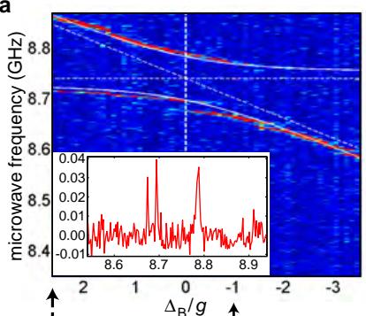
As a first demonstration of strongly coupled circuit QED in our system, these two basic vacuum Rabi behaviors were independently verified for each qubit, A and B. In Fig. 2a, we show an example of the vacuum Rabi splitting for qubit B (a similar splitting was obtained for qubit A) using well established spectroscopic techniques24, 27. Vacuum Rabi oscillations were also obtained for both qubits using an analogous technique borrowed from quantum optics28 and utilized previously27 for a superconducting flux qubit coupled to a lumped-element cavity21. With qubit B fixed at a given detuning , a fast (∼ 4 ns) π pulse was applied to the qubit inducing vacuum Rabi oscillations with a raw contrast of ∼ 20 %, visible out to 200 ns. In Fig. 2b, we show an example of vacuum Rabi oscillations for qubit B (similar oscillations were obtained for qubit A) for various detunings . We see an increase in the vacuum Rabi frequency with detuning, roughly as , with a minimum value on resonance . An additional energy splitting, near the cavity resonance (seen in Fig. 2a on the lower spectroscopic branch) caused by a two-level system (TLS) defect common to large area Josephson phase qubits24, 27, is responsible for a slight broadening of the spectroscopic splitting and a beating in the oscillations centered at . Numerical calculations taking into account the size and position of the TLS agree well with the data for , where a small amount of beating is still visible on resonance (see the inset of Fig. 2b). Both qubits showed similar behavior (without a nearby TLS in qubit A), different by less than 10 %, with a coupling strength matching the design values (see Fig. 1). After calibrating the amplitude of the shift pulses separately, for both qubits at their far-detuned operation points, we remeasured the vacuum Rabi oscillations using the shift pulse sequence described in Fig. 2c. Both experimental methods gave similar results with a reduced contrast due to nonoptimized shift pulse shaping and induced Landau-Zener transitions between the qubit and distributed TLS defects27.
In order to investigate the transfer of quantum states through the resonant cavity, we utilize the vacuum Rabi interaction of both qubits. The complete sequence (i-v) is described in Fig. 2c. Using the static, dc flux bias coils the phase qubits are completely detuned from the cavity and each other to suppress any stray cavity and qubit interactions. In this configuration, we first, (i) prepare a superposition state for qubit A using a rapid microwave pulse. Next, (ii) we apply a shift pulse to qubit A, placing it on resonance with the cavity for a time duration With shift pulse speeds much greater than but still much less than (still adiabatic), we effectively preserve the initially prepared quantum state until , when the vacuum Rabi oscillations begin to mix the qubit-cavity states. (iii) With the detuning of qubit A restored, we wait for a short storage time ns before, (iv) a second shift pulse places qubit B on resonance with the cavity for a time . Finally, (v) qubit B is returned to its fully detuned position and both qubits are measured simultaneously using a fast (∼ 4 ns) flux bias measurement pulse11, 27 that reveals the excited state occupation probabilities and corresponding to qubits A and B, respectively.
For the the experimental data shown in Fig. 3, we used the state transfer protocol as outlined in Fig. 2c with an initial microwave π-pulse applied to qubit A to create a simple pure state for transfer. Fig. 3a,b show data over a range of interaction times and . The population maxima (color scale) in the target qubit B in Fig. 3b satisfy the following conditions: whenever is an odd half-multiple of a vacuum Rabi period, qubit A has a low population and we see a corresponding vacuum Rabi oscillation of occurring in qubit B. The experimental data is in good agreement with theoretical calculations of equation (1) under ideal conditions, Fig. 3c,d.
For clarity, we have extracted a set of three curves from the color plots of Fig. 3a,b (arrows) and displayed them in Fig. 3e,f. If both shift pulses last for a half vacuum Rabi period then the qubit photon is completely transferred into the cavity and the subsequent excited state population is low, while in the target qubit B, we simultaneously observe clear vacuum Rabi oscillations (black curve). The fact that the oscillations start from a minimum indicates the presence of a photon in the cavity at the moment of state transfer to qubit B, as expected. Thus, the photon must leave qubit A, enter the cavity, where it is stored for a short time, and then be finally deposited in qubit B. Repeating this experiment for a full vacuum Rabi period ns, green curves) shows no oscillations in , also as expected, since the photon was fully returned to qubit A (as indicated by higher values of , leaving the cavity empty. The red lines illustrate an intermediate case, with of a vacuum Rabi period yielding oscillations of lower amplitude but the same frequency. Thus, we conclude that we can clearly transfer photons between two phase qubits, through the resonant cavity, as well as store this quantum information for a short time. Because superconducting cavities tend to be more coherent than state-of-the-art qubits, due to their simplicity, well defined, well separated, and fixed resonant modes, extremely high quality factor superconducting microwave resonators29 may provide us with a feasible long-term memory element for superconducting quantum information systems.
In order to verify that quantum coherence is maintained during state transfer for an arbitrary superposition state, we perform a Ramsey fringe-type interference experiment7 that preserves the quantum state up to a relative phase factor. We follow a protocol (Fig. 4a) similar to that used previously, except here, we first prepare qubit A in an equal-weight superposition state using pulse applied slightly off-resonance, , where is the microwave drive frequency. Again, we perform shift pulses in order, first, to map the initial state onto a superposition of the two lowest photon number states |0i and |1i of the cavity and, second, to retrieve this quantum information through the transfer to the states and spanned by qubit B. Following the coherent state transfer to qubit we expect a clear precession of the transferred state, , during the time delay , where we have accumulated a relative phase shift Θ during the transfer process. By applying a final pulse to qubit (also slightly off-resonance, , we complete the Ramsey fringe-type experiment, rotating qubit B into a different state depending on the total relative phase shift accumulated over the time . In Fig. 4b,c, we show the expected Ramsey-type oscillations with frequencies linearly proportional to the microwave detuning , thus verifying the transfer of quantum coherence through the cavity qubus.
In order to test the integrity of our experimental design, we investigated in detail the possible role of stray unintended photon generation in the cavity, both dc and rf inductive flux crosscoupling between the two qubits, the role of nearby TLS defects, and measurement cross-talk11 directly through the cavity. First, we verified that the experiment satisfied basic consistency checks based on predictions of the model hamiltonian, equation (1), by altering the transfer pulse sequence shown in Fig. 2c. When we applied π pulses to either qubit with any of the shift pulses omitted, we saw no visible oscillations (above 1 % contrast) in the target qubit. When compared to the ∼ 20 % contrast of the full state transfer sequence, this corresponds to less than 0.05 stray photons in the cavity per π pulse. Next, we determined the cross coupling of shift pulses by studying the flux modulation of one qubit for flux applied to the other qubit. We found a leakage ratio of at most 6 % between the two qubits, allowing us to avoid bias pulse cross-talk for large detunings. We performed numerical simulations that included the finite coherence times of each qubit, nearby TLS defects and no additional cross talk. These results agree with the data as shown in Fig. 2. Finally, we performed detailed time delay measurements11 in order to investigate the role of measurement cross-talk when qubits A and B were not measured simultaneously. These results show that using shift pulses, which allows both qubits to be far detuned during measurement, and the resonant cavity significantly reduce measurement cross-talk. In this cavity-coupled phase qubit system, the resonator between the qubits acts like an extremely narrow bandpass filter (centered at its resonant frequency) which helps block either qubit from the broadband transient microwave excitations generated by the measurement process11.
We have successfully coupled two superconducting Josephson phase qubits through a resonant microwave cavity and have observed vacuum Rabi splittings, vacuum Rabi oscillations, and the coherent transfer and storage of quantum states mediated by the cavity. We estimate that the fidelity of the state transfer protocol is mostly limited by the quality of the phase qubits, the presence of TLS defects, and the nonoptimization of the shape of the shift pulses performing the state transfer. It is clear that further measurements involving full state tomography10 with higher quality qubits must be performed in order to fully quantify the fidelity of this cavity qubus. This simple demonstration, however, clearly shows progress towards the storage and communication of quantum information using coherent superconducting systems of multiple qubits, an exciting new frontier for solid state circuit QED and quantum information science.
Acknowledgements We gratefully acknowledge fruitful discussions with J. Aumentado, K. Cicak, K. Osborne, R. Schoelkopf and David Wineland. This work was financially supported by NIST and DTO under grant number W911NF-05-R-0009. Contribution of the U.S. government, not subject to copyright.
Competing interests statement The authors declare that they have no competing financial interests.
Correspondence and requests for materials should be addressed to simmonds@boulder.nist.gov
-
Julsgaard, B., Sherson, J., Cirac, J. I., Fiurek, J. & Polzik, E. S. Experimental demonstration of quantum memory for light. Nature 432, 482–486 (2004).
-
Langer, C. et al. Long-lived qubit memory using atomic ions. Phys. Rev. Lett. 95, 060502 (2005).
-
Plastina, F. & Falci, G. Communicating Josephson qubits. Phys. Rev. B 67, 224514 (2003).
-
Cleland, A. N. & Geller, M. R. Superconducting qubit storage and entanglement with nanomechanical resonators. Phys. Rev. Lett. 93, 070501 (2004).
-
Bouchiat, V. et al. Quantum coherence with a single Cooper pair. Phys. Scr. T76, 165–170 (1998).
-
Nakamura, Y., Pashkin, Yu. A. & Tsai, J. S. Coherent control of macroscopic quantum states in a single-Cooper-pair box. Nature 398, 786–788 (1999).
-
Vion, D. et al. Manipulating the quantum state of an electrical circuit. Science 296, 886 (2002).
-
Chiorescu, I., Nakamura, Y., Harmans, C. J. & Mooij, J. E. Coherent quantum dynamics of a superconducting flux qubit. Science 299, 1869–1871 (2003).
-
Makhlin, Yu., Schon, G. & Shnirman, A. Quantum-state engineering with Josephson-junction ¨ devices. Rev. Mod. Phys. 73, 357–400 (2001).
-
Yamamoto, T., Pashkin, Y. A., Astafiev, O., Nakamura, Y. & Tsai, J. S. Quantum oscillations in two coupled charge qubits. Nature 425, 941 (2003).
-
McDermott, R. et al. Simultaneous state measurement of coupled Josephson phase qubits. Science 307, 1299–1302 (2005).
-
Steffen, M. et al. Measurement of the entanglement of two superconducting qubits via state tomography. Science 313, 1423–1425 (2006).
-
Grajcar, M. et al. Four-qubit device with mixed couplings. Phys. Rev. Lett. 96, 047006 (2006).
-
Haroche, S. & Raimond, J.-M. Exploring the quantum: atoms, cavities, and photons (Oxford University Press, Oxford, 2006), 1st edn.
-
Schleich, W. P. & Walther, H. Elements of quantum information (Wiley-VCH, New York, 2007), 1st edn.
-
Maˆıtre, X. et al. Quantum memory with a single photon in a cavity. Phys. Rev. Lett. 79, 769–772 (1997).
-
Buisson, O. & Hekking, F. W. J. In Averin, D. V., Ruggiero, B. & Silvestrini, P. (eds.) Macroscopic Quantum Coherence and Quantum Computing, 137–145 (Kluwer Academic, New York, 2001).
-
Blais, A., Huang, R.-S., Wallraff, A., Girvin, S. M. & Schoelkopf, R. J. Cavity quantum electrodynamics for superconducting electrical circuits: An architecture for quantum computation. Phys. Rev. A 69, 062320 (2004).
-
Wallraff, A. et al. Strong coupling of a single photon to a superconducting qubit using circuit quantum electrodynamics. Nature 431, 162–167 (2004).
-
Chiorescu, I. et al. Coherent dynamics of a flux qubit coupled to a harmonic oscillator. Nature 431, 159 (2004).
-
Johansson, J. et al. Vacuum Rabi oscillations in a macroscopic superconducting qubit LC oscillator system. Phys. Rev. Lett. 96, 127006 (2006).
-
Koch, R. H. et al. Experimental demonstration of an oscillator stabilized Josephson flux qubit. Phys. Rev. Lett. 96, 127001 (2006).
-
Xu, H. et al. Spectroscopy of three-particle entanglement in a macroscopic superconducting circuit. Phys. Rev. Lett. 94, 027003 (2005).
-
Simmonds, R. W. et al. Decoherence in Josephson phase qubits from junction resonators. Phys. Rev. Lett. 93, 077003 (2004).
-
Martinis, J. M., Nam, S., Aumentado, J. & Urbina, C. Rabi oscillations in a large Josephsonjunction qubit. Phys. Rev. Lett. 89, 117901 (2002).
-
Pozar, D. M. Microwave engineering (Addison-Wesley, New York, 1990), 1st edn.
-
Cooper, K. B. et al. Observation of quantum oscillations between a Josephson phase qubit and a microscopic resonator using fast readout. Phys. Rev. Lett. 93, 180401 (2004).
-
Brune, M. et al. Quantum Rabi oscillation: A direct test of field quantization in a cavity. Phys. Rev. Lett. 76, 1800–1803 (1996).
-
Day, P. K., LeDuc, H. G., Mazin, B. A., Vayonakis, A. & Zmuidzinas, J. A broadband superconducting detector suitable for use in large arrays. Nature 425, 817–821 (2003).
a
b
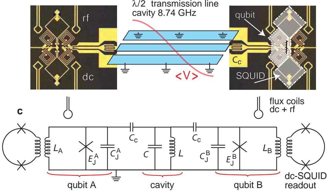
Figure 1: a, Potential energy diagram of the phase qubit and illustration of the measurement, where tunneling of the qubit excited state |ei results in a difference of about one flux quantum in the loop, which is read out by a dc . We determine the excited state population and of qubit A and B by repeating simultaneous single shot thousands of times. b, Illustration of the quantum memory element with two Josephson phase qubits (with junction areas connected via coupling capacitors fF to either end of a resonant cavity formed by a 7 mm long slowly meandering coplanar waveguide, with the qubits separated by about 1.1 mm. The red line depicts the voltage amplitude of the lowest . The device was fabricated with standard optical lithography, producing junctions on a sapphire substrate, using as an insulator between the metallic layers. c, Lumped element equivalent circuit near the resonance. The cavity has an effective inductance pH and capacitance , and both qubits had roughly nH,
a
PB
c
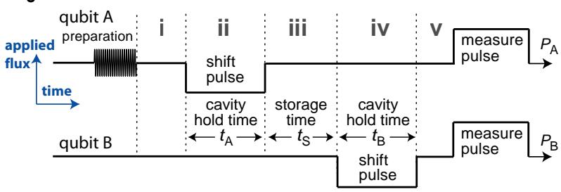
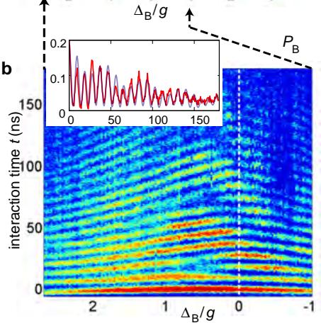
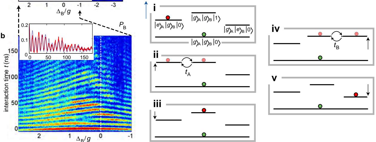
Figure 2: a, Microwave spectroscopy of qubit B showing the vacuum Rabi splitting (qubit A detuned). Blue color represents low , red represents high . The inset shows a cross-section at (along the dashed line). b, Vacuum Rabi oscillations in qubit B after a short pulse. The inset shows a cross-section at . The blue line shows the numerical results including the TLS defect near resonance. c, Illustration of the general quantum state transfer protocol performed by a sequence of flux bias pulses applied to qubit A and B. Here each qubit is effectively decoupled from the cavity, except during the shift pulses, which bring them into resonance with the cavity, one qubit at a time. i, An arbitrary superposition state is prepared in qubit A. The red and green shaded circles represent mixtures of the occupied energy levels. ii, Qubit A is shifted into resonance with the cavity for an interaction time lasting one half of a vacuum Rabi period, , the photon has been exchanged and the state of qubit A has been mapped into a superposition i of the two lowest photon number eigenstates (Fock states) of the cavity. iii, Qubit A is shifted off resonance, storing the initial state in the cavity for a time duration . iv, Qubit B is shifted into resonance for one half of a vacuum Rabi period, , transferring the state into qubit B, leaving the cavity in its ground state |0i. v, Both qubits are detuned, completing the coherent quantum state transfer from qubit A to qubit B.
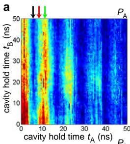
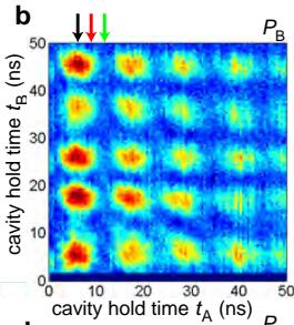
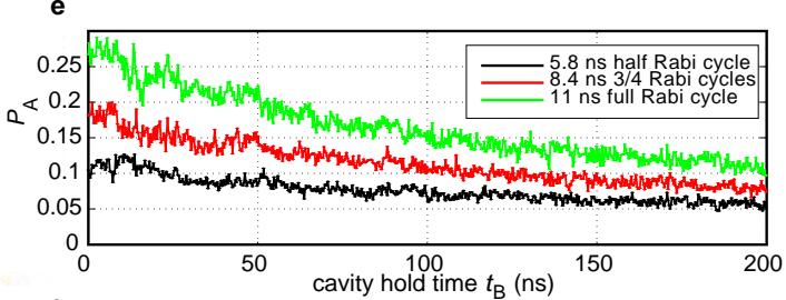
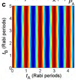
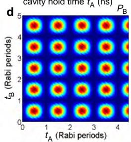
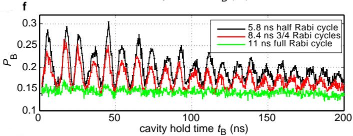
Figure 3: Experimental data showing the quantum state transfer from qubit A to B via the cavity, according to the protocol in Fig. 2, where the qubit A excited state is first mapped into the single photon state |1i in the cavity, and then transferred into qubit B. a,b, Measured populations of qubits A and B as functions of the cavity hold times. Blue color represents low , red represents high d, Corresponding theoretical prediction for ideal conditions without decoherence and 100 % fidelity. e, Excited state occupancy of the source qubit A reveals a lower population if the interaction time equals one half of a vacuum Rabi period, (black). f, Simultaneous measurement of qubit B shows vacuum Rabi oscillations induced by the transfer of a single photon (black). Here the black, red, and green curves in e (f) correspond to data indicated by the arrows in a (b). For a full discussion see the text.
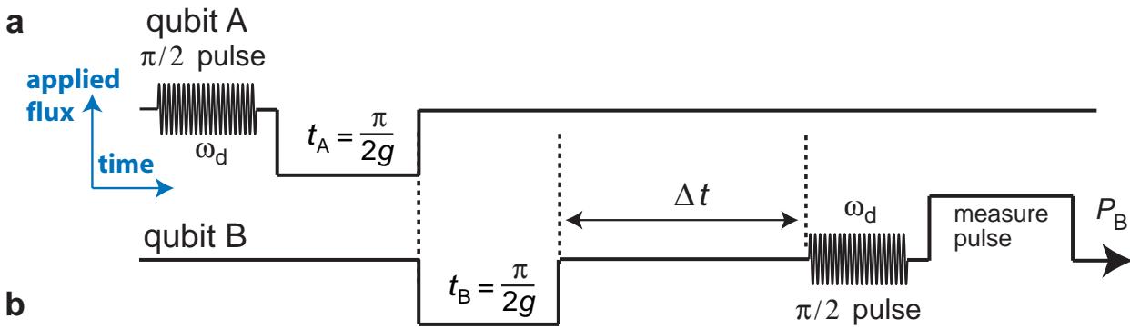
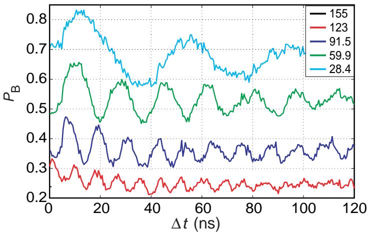
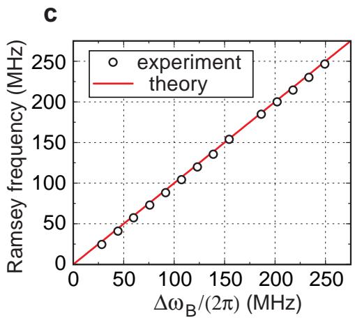
Figure 4: Demonstration of the coherent transfer of a quantum state through the quantum bus. We use microwave pulses detuned from the level spacing frequencies of qubits A and B in order to perform a Ramsey fringe-type interference experiment. a, We prepare an equal weight superposition state in qubit A using a 10 ns long pulse (with frequency while both qubits are detuned from the cavity and from each other. We transfer this state into qubit B as in Fig. 2, and then wait for a delay time before applying a detuned pulse to qubit B. This is analogous to Ramsey fringe experiments with single qubits, where a coherent quantum state slowly precesses at the microwave detuning frequency . b, Coherent oscillations in qubit B for several detunings (vertically displaced for clarity). c, The frequency of the Ramseytype oscillations as a function of the microwave detuning. The solid line represents the theoretical predictions with no fitting parameters.